Accel 6 click is a three-axis acceleration sensor with many features. It uses the BMA280, a 14bit triaxial acceleration sensor with intelligent on-chip motion triggered interrupt controller, from Bosch Sensortec. This sensor has an advanced set of features, that allows easy acceleration measurement in three perpendicular axes for up to ±16g, with selectable max range steps for increased accuracy. Using lowpass filter allows filtering of the abrupt changes in acceleration readings. FIFO buffer ensures reliable and fast data delivery. Intelligent interrupt engine allows detection of motion, inactivity, shock vibration, new data arrival, and more.
Equipped with the BMA280 advanced acceleration sensor, this Click board™ can be used in a wide range of applications that require low power consumption, fast response, and reliability of the acceleration sensor. It can be used for display orientation, HID applications, drop detection applications (for warranty logging), pedometer, step counter and similar applications that rely on the reliable acceleration and motion-sensing provided by this Click board™.
How does it work?
Accel 6 click carries the BMA280, a 14bit triaxial acceleration sensor with intelligent on-chip motion triggered interrupt controller, from Bosch Sensortec. This is advanced motion and an acceleration sensor, with many features aimed towards simplifying the operation and firmware development. The BMA280 sensor consists of the ASIC circuitry, which converts the output of the microelectromechanical sensing element (MEMS). Both filtered and unfiltered data streams are available for reading. The fastest refresh rate of the unfiltered stream is up to 2kHz, while the refresh rate of the filtered output depends on the selected filter bandwidth. The BMA280 device also offers a thermal measurement sensor. with the resolution of 0.5°C.
The acceleration data width is 14 bits. The filtering can be selected in several steps, with the bandwidth configuration from 8Hz up to 500Hz. The selected bandwidth configuration also affects the refresh rate, resulting in up to 64ms between consequent readings for the 8Hz setting. The unfiltered stream takes up to 0.5ms between readings.
The range selection affects the size of the measurement steps. There are four different acceleration measurement ranges that can be selected: ±2g, ±4g, ±8g, and ±16g. The step size of the ranges varies between ±0.244mg (±2g range) and ±0.977mg (±16g range).
Up to eight configurable interrupts are available, allowing tap sensing, orientation detection, motion detection, slope detection, new data availability, and more. The interrupt event is reported by the appropriate bit in the Status Register (flag). The interrupt controller allows the interrupt flags to be set in a range of different ways: the interrupt flag bit can be latched, non-latched, and temporal, with predetermined timings. The interrupt inputs can be both filtered and unfiltered readings, allowing optimal settings to be used for simplified firmware development.
The BMA280 sensor offers three different offset compensation methods: slow, fast, manual compensation, as well as the inline calibration. The offset compensation is performed with the unfiltered values, but it is applied to both data streams as well. The offset compensation is important for getting reliable data since the offset in readings might appear for a number of reasons. Compensation values are generated internally, but can also be manually written, or stored in the NV memory for using them after POR.
This device is also equipped with the NV memory, which is used to store working parameters to locations which will not be reset after the Power ON Reset event (POR). There are eight NV registers, with four of them corresponding to the offset related operations and two of them for general purpose. The offset related register values are loaded to the appropriate volatile mirror locations after each POR.
There are six power modes available, offering a different set of options and working parameters. The device can be set as the normal mode, deep suspend mode, suspend mode, standby mode, low power mode 1, and low power mode 2. All these modes allow flexible selection of the power consumption vs performance to be selected.
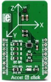
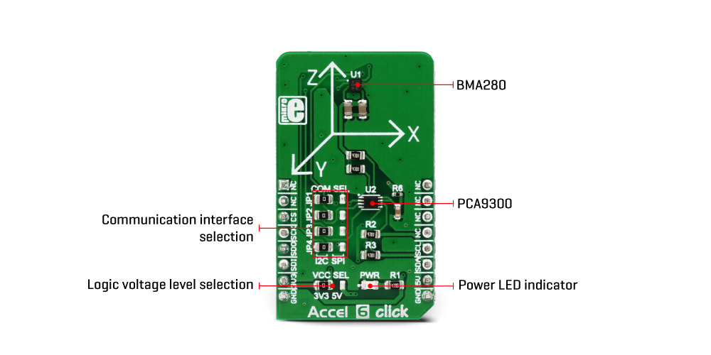
The Click board™ offers both I2C and SPI communication interface. By moving the group of jumpers labeled as COM SEL, it is possible to choose between I2C or SPI interface. Note that all the jumpers have to be moved to the same side. Otherwise, the device might become unresponsive.
Accel 6 click is powered via the mikroBUS™ +3.3V rail. However, it offers a logic voltage selection, via the VCC SEL jumper. Since the BMA280 sensor cannot operate with signals up to 5V, a level shifting IC is used to allow both 3.3V and 5V MCUs to be interfaced with this Click board™. The VCC SEL jumper routes either 3.3V or 5V to the voltage reference pin of the PCA9306, a dual bidirectional level shifting IC.
Specifications
| Type |
Motion |
| Applications |
It can be used for display orientation, HID applications, drop detection applications (for warranty logging), pedometer, step counter, and similar applications that rely on reliable acceleration and motion-sensing. |
| On-board modules |
BMA280, a 14bit triaxial acceleration sensor with intelligent on-chip motion triggered interrupt controller, from Bosch Sensortec; PCA9306, a dual bidirectional I2C level shifting IC, from Texas Instruments. |
| Key Features |
Advanced interrupt engine allows detection of various events, on-chip data filtering prevents abrupt changes of readings, offset calibration can be stored in the non-volatile memory locations, etc. |
| Interface |
I2C,SPI |
| Input Voltage |
3.3V,5V |
| Click board size |
M (42.9 x 25.4 mm) |
Pinout diagram
This table shows how the pinout on Accel 6 click corresponds to the pinout on the mikroBUS™ socket (the latter shown in the two middle columns).
| Notes | Pin |  | Pin | Notes |
|---|
|
NC |
1 |
AN |
PWM |
16 |
NC |
|
|
NC |
2 |
RST |
INT |
15 |
NC |
|
| SPI Chip Select |
CS |
3 |
CS |
RX |
14 |
NC |
|
| SPI Clock |
SCK |
4 |
SCK |
TX |
13 |
NC |
|
| SPI Data OUT |
SDO |
5 |
MISO |
SCL |
12 |
SCL |
I2C Clock |
| SPI Data IN |
SDI |
6 |
MOSI |
SDA |
11 |
SDA |
I2C Data |
| Power supply |
3.3V |
7 |
3.3V |
5V |
10 |
5V |
Power supply |
| Ground |
GND |
8 |
GND |
GND |
9 |
GND |
Ground |
Accel 6 click electrical specifications
| Description | Min | Typ | Max | Unit |
|---|
| Acceleration measurement range |
±2 |
- |
±16 |
g |
| Output refresh rate |
8 |
- |
2000 |
Hz |
| Thermal measurement range |
-40 |
- |
+85 |
°C |
Onboard settings and indicators
| Label | Name | Default | Description |
|---|
| LD1 |
PWR |
- |
Power LED indicator |
| JP1-JP4 |
COM SEL |
Left |
Communication interface selection: left position I2C, right position SPI |
| JP5 |
VCC SEL |
Left |
Logic voltage level selection: left position 3.3V, right position 5V |
Software support
We provide a demo application for Accel 6 click on our Libstock page, as well as a demo application (example), developed using MikroElektronika compilers. The demo can run on all the main MikroElektronika development boards.
Library Description
The library initializes and defines the I2C bus driver and drivers that offer a choice for writing data in the register. The library includes the function for reading the X/Y/Z axis data, orient chip, detect tap and slope on the chip and function for reading the temperature data. The user also has the function for initializes chip, set offset and software reset.
Key functions:
float accel6_getAxis(uint8_t axis) - Functions for reading the axis data.void accel6_getOrient(uint8_t *z_orient, uint8_t *xy_orient) - Functions for reading the orient.uint8_t accel6_getTapStatus() - Functions for detect tap on the x/y/z axis.
Example description
The application is composed of three sections:
- System Initialization - Initializes I2C module.
- Application Initialization - Initializes Driver init and settings accelerometer data range, bandwidth, mode and sleep timer which are necessary for the Init chip.
- Application Task - (code snippet) - Reads the Accel X / Y / Z axis data in mg,
Temperature data in C, detects the orientation of the X, Y, and Z axis
and checking on which axis the tap is detected.
All data logs on USB UART for every 500 ms.
void applicationTask()
{
 mikrobus_logWrite(" X axis : ", _LOG_TEXT);
 fAxis = accel6_getAxis(_ACCEL6_AXIS_X);
 FloatToStr(fAxis, demoText);
 mikrobus_logWrite(demoText, _LOG_TEXT);
 mikrobus_logWrite(" mg ", _LOG_LINE);

 mikrobus_logWrite(" Y axis : ", _LOG_TEXT);
 fAxis = accel6_getAxis(_ACCEL6_AXIS_Y);
 FloatToStr(fAxis, demoText);
 mikrobus_logWrite(demoText, _LOG_TEXT);
 mikrobus_logWrite(" mg ", _LOG_LINE);

 mikrobus_logWrite(" Z axis : ", _LOG_TEXT);
 fAxis = accel6_getAxis(_ACCEL6_AXIS_Y);
 FloatToStr(fAxis, demoText);
 mikrobus_logWrite(demoText, _LOG_TEXT);
 mikrobus_logWrite(" mg ", _LOG_LINE);

 mikrobus_logWrite(" Temperature : ", _LOG_TEXT);
 Temp = accel6_getTemperature();
 FloatToStr(Temp, demoText);
 mikrobus_logWrite(demoText, _LOG_TEXT);
 mikrobus_logWrite(" C ", _LOG_LINE);

 accel6_getOrient(&z_orient[0], &xy_orient[0]);

 switch(z_orient[0])
 {
 case 1:
 {
 mikrobus_logWrite(" Z orient : UPWARD looking ", _LOG_LINE);
 break;
 }
 case 2:
 {
 mikrobus_logWrite(" Z orient : DOWNWARD looking ", _LOG_LINE);
 break;
 }
 default:
 {
 break;
 }
 }

 switch(xy_orient[0])
 {
 case 1:
 {
 mikrobus_logWrite(" XY orient : UPSIDE DOWN ", _LOG_LINE);
 break;
 }
 case 2:
 {
 mikrobus_logWrite(" XY orient : LANDSCAPE LEFT ", _LOG_LINE);
 break;
 }
 case 3:
 {
 mikrobus_logWrite(" XY orient : LANDSCAPE RIGHT ", _LOG_LINE);
 break;
 }
 case 4:
 {
 mikrobus_logWrite(" XY orient : UPRIGHT ", _LOG_LINE);
 break;
 }
 default:
 {
 break;
 }
 }

 tap_detect = accel6_getTapStatus();
 switch( tap_detect )
 {
 case 1:
 {
 mikrobus_logWrite(" Tap status : X negative ", _LOG_LINE);
 break;
 }
 case 2:
 {
 mikrobus_logWrite(" Tap status : Y negative ", _LOG_LINE);
 break;
 }
 case 3:
 {
 mikrobus_logWrite(" Tap status : Z negative ", _LOG_LINE);
 break;
 }
 case 4:
 {
 mikrobus_logWrite(" Tap status : X positive ", _LOG_LINE);
 break;
 }
 case 5:
 {
 mikrobus_logWrite(" Tap status : Y positive ", _LOG_LINE);
 break;
 }
 case 6:
 {
 mikrobus_logWrite(" Tap status : Z positive ", _LOG_LINE);
 break;
 }
 default:
 {
 break;
 }
 }

 mikrobus_logWrite(" ", _LOG_LINE);
 Delay_ms( 500 );
}
The full application code, and ready to use projects can be found on our Libstock page.
Other MikroElektronika libraries used in the example:
Additional notes and information
Depending on the development board you are using, you may need USB UART click, USB UART 2 click or RS232 click to connect to your PC, for development systems with no UART to USB interface available on the board. The terminal available in all MikroElektronika compilers, or any other terminal application of your choice, can be used to read the message.
mikroSDK
This click board is supported with mikroSDK - MikroElektronika Software Development Kit. To ensure proper operation of mikroSDK compliant click board demo applications, mikroSDK should be downloaded from the LibStock and installed for the compiler you are using.
For more information about mikroSDK, visit the official page.