Due to its large scale of integration, this sensor requires no external components involved in the measurement process, which improves the overall accuracy. Each of these sensors is factory tested and calibrated. The sensor also offers several I/O pins for simplified configuration and operation, saving the MCU from polling the registers. A specialized ALARM pin offers the possibility to trigger an MCU interrupt if the programmed CO2 concentration value is exceeded. These features make the NDIR CO2 click a perfect solution for various CO2 measuring applications, such as air conditioning applications, indoor air quality control applications, automatic fresh air exchange and venting systems, and similar.
How does it work?
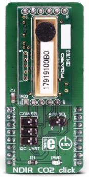
The main component on the NDIR CO2 click is the CDM7160, a pre-calibrated single light source, dual wavelength, CO2 sensing system, by Figaro Engineering, INC. Its light source emits the light, which is detected by two IR sensors. One light sensor is placed behind the filter which allows only a part of the IR spectrum affected by the CO2 gas to pass through, while the second sensor is placed behind the filter which passes the IR spectrum of the light which is not affected by the CO2 gas. This forms a kind of a differential input for the sensor - an integrated MCU will process the received data by differentiating these readings. This allows the absolute value of the CO2 gas concentration to be obtained, but also removes any influences of particles and other disturbances, as they affect both sensors equally. This allows consistent readings over various temperatures, in various environments, including areas rich with corrosive gases (SO2, H2S…), and over a longer period of times (aging).
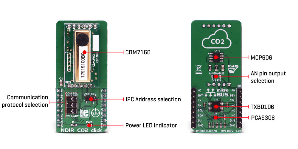
The CDM7160 sensor has the ability to output data in two ways: depending on the status of the MSEL pin, it can use either a UART or I2C communication interface. If this pin is pulled to a LOW logic level, the I2C interface will be selected after the CDM7160 reset cycle. Otherwise, the UART interface will be selected. Since the communication pins are shared between the interfaces (SCL/RX and SDA/TX), they need to be switched to the corresponding pins of the mikroBUS™ whenever the different type of communication is used. Therefore, the Click board™ has a section with three small SMD slide switches labeled as COM SEL. Positioning all three switches to the LEFT position will select the I2C interface while the RIGHT position will select the UART interface. When the I2C interface is selected, an additional pin is available to set up the I2C address of the device. This pin determines the LSB of the I2C slave address and when it is pulled to a LOW logic level, this bit becomes 0. This allows up to 2 different devices to be connected to the same I2C bus. This pin is routed to another SMD slide switch, labeled as the ADD SEL.
It is possible to perform two types of calibration for this sensor: zero calibration and the background calibration. The zero calibration is performed in the atmosphere with the CO2 concentration of 0 ppm, while the background calibration is performed in the atmosphere with a nominal CO2 value (400 ppm). Since the sensor is influenced by the sea level and the atmospheric pressure, these calibrations should be performed whenever these conditions are changed. This will allow an increased accuracy of the CO2 concentration readings. The CDM7160 sensor offers a pin labeled as CAL, for an easy calibration: if the CAL pin is pulled to a LOW logic level for about 2 to 11 seconds, a background calibration will be performed. If pulled to a LOW logic level for more than 12 seconds, the zero calibration will be performed. This pin should remain HIGH during normal operation. An internal pull-up resistor ensures that the pin is always HIGH if it remains floating. This pin is routed to the mikroBUS™ CS pin, labeled as CAL
The ALERT pin of the CDM7160 sensor is used to trigger an interrupt on the host MCU. By default, it will trigger an interrupt if the CO2 concentration exceeds 1000ppm. The interrupt will be cleared if the concentration drops below 900ppm. These settings can be changed by writing values to the corresponding ALHI and ALLO registers (upper and lower threshold registers). The ALERT pin of the CDM7160 sensor is routed to the mikroBUS™ INT pin.
BUSY pin of the sensor provides means to save the sensor from polling sensor registers in order to verify if the device is ready for the communication. By setting an interrupt for the BUSY pin, the MCU can be automatically triggered only when the sensor is ready to accept a new command. A logic LOW level signals the MCU that the sensor is unable to accept a new command. The sensor might be unavailable while processing the data internally, for about 0.3 seconds. This pin is routed to the mikroBUS™ RST pin, labeled as BSY on the Click board™.
Besides UART and I2C communication, the sensor offers a 1KHz PWM signal of with the duty cycle which depends on the CO2 concentration (0 to 5000 ppm of CO2). The Click board™ is equipped with an operational amplifier, which averages the PWM signal, offering analog DC voltage (0 to 5V) on its output, directly proportional to the pulse width of the PWM signal. By switching the SMD jumper labeled as AN ENABLE to EN position, the voltage at the output of this operational amplifier becomes available at the AN pin of the mikroBUS™. By default, the jumper is soldered to DIS position. Note that the full-scale voltage on the operational amplifier output is 5V (5000 ppm of CO2 equals 5V)
To allow communication with 3.3V MCUs, two additional ICs are used: one is the PCA9306, which translates voltage levels of the I2C signals, while the second IC is the TXB0106, used to translate voltage levels of the remaining IC pins, including the UART. Both of these ICs are used on many other designs, and are proven to be very reliable solution.
Specifications
| Type |
Gas |
| Applications |
It is a perfect solution for various CO2 measuring applications, such as air conditioning applications, indoor air quality control applications, automatic fresh air exchange and venting system applications, and similar. |
| On-board modules |
CDM7160, a CO2 sensing system, by Figaro Engineering, INC; PCA9306, a dual bidirectional I2C bus voltage translator; TXB0106, a 6bit bidirectional level shifter, both from Texas Instruments; MCP606, a rail-to-rail op-amp by Microchip |
| Key Features |
NDIR sensor which uses dual IR sensors which allow differential reading of CO2 concentration, provides absolute CO2 gas concentration levels, long term stability, accuracy and immunity to interferences and pollution, offers several I/O interface types. |
| Interface |
Analog,I2C,UART |
| Input Voltage |
3.3V,5V |
Pinout diagram
This table shows how the pinout on NDIR CO2 click corresponds to the pinout on the mikroBUS™ socket (the latter shown in the two middle columns).
| Notes | Pin |  | Pin | Notes |
|---|
| Analog OUT |
AN |
1 |
AN |
PWM |
16 |
NC |
|
| Busy status |
BSY |
2 |
RST |
INT |
15 |
INT |
Alarm OUT |
| Calibration |
CAL |
3 |
CS |
RX |
14 |
TX |
UART TX |
|
NC |
4 |
SCK |
TX |
13 |
RX |
UART RX |
|
NC |
5 |
MISO |
SCL |
12 |
SCL |
I2C Clock |
|
NC |
6 |
MOSI |
SDA |
11 |
SDA |
I2C Data |
| Power supply |
3.3V |
7 |
3.3V |
5V |
10 |
5V |
Power supply |
| Ground |
GND |
8 |
GND |
GND |
9 |
GND |
Ground |
Onboard jumpers and settings
| Label | Name | Default | Description |
|---|
| PWR |
PWR |
- |
Power LED indicator |
| SW1 - SW3 |
ADD SEL |
Left |
Communication protocol selection: left position I2C, right position UART |
| SW4 |
ADD SEL |
Left |
I2C address LSB selection: left position 0, right position 1 |
| JP1 |
AN ENABLE |
Left |
AN pin output selection: left position AN disabled, right position AN enabled |
H-Bridge click electrical specifications
| Description | Min | Type | Max | Unit |
|---|
| Voltage at the AN pin (if enabled) |
0 |
- |
5 |
V |
| Measurement range |
300 |
- |
5000 |
ppm |
| Averaging interval |
- |
2 |
- |
s |
Software support
We provide a demo application for NDIR CO2 click on our Libstock page, as well as a demo application (example), developed using MikroElektronika compilers. The demo can run on all the main MikroElektronika development boards.
Library Description
Library initializes and defines I2C driver and performs writing to registers and reading from registers. Also has the ability to measure CO2 concentration in ppm unit. For more details check the documentation.
Key functions:
uint8_t ndirco2_writeReg( uint8_t register_address, uint8_t transfer_data ) - The function writes one byte of data to register.uint8_t ndirco2_readReg( uint8_t register_address, uint16_t *dataOut ) - The function reads data from a register.void ndirco2_readCO2( uint8_t setCheckMode, uint16_t *outputData ) - The function reads 15-bit CO2 concentration data from data registers, only when data is ready for reading after each measurement, or after the number of consecutive measurements determined by the AVE register + 1 is exceeded.
Example description
The application is composed of three sections:
- System Initialization - Initializes peripherals and pins.
- Application Initialization - Initializes I2C driver and performs driver reset and determines
a number of averaging measurements.
- Application Task - (code snippet) - Reads CO2 concentration data in ppm unit after each completed measurement. One measurement is finished after 300 ms, and the period between the two measurements is 2 seconds. Results of measurements logs on USBUART.void applicationTask()
void applicationTask()
{
 ndirco2_readCO2( _NDIRCO2_CHECK_EACH_MEASURE, &co2Data );
 WordToStr( co2Data, text );
 mikrobus_logWrite( "CO2 concentration is: ", _LOG_TEXT );
 mikrobus_logWrite( text, _LOG_TEXT );
 mikrobus_logWrite( "ppm", _LOG_LINE );
}
The full application code, and ready to use projects can be found on our Libstock page.
Other MikroElektronika libraries used in the example:
Additional notes and information
Depending on the development board you are using, you may need USB UART click, USB UART 2 click or RS232 click to connect to your PC, for development systems with no UART to USB interface available on the board. The terminal available in all MikroElektronika compilers, or any other terminal application of your choice, can be used to read the message.
mikroSDK
This click board is supported with mikroSDK - MikroElektronika Software Development Kit. To ensure proper operation of mikroSDK compliant click board demo applications, mikroSDK should be downloaded from the LibStock and installed for the compiler you are using.
For more information about mikroSDK, visit the official page.