7x10 G click can be used for displaying letters on a display with 7x5 font resolution. It carries a matrix of 70 green LEDs driven by a pair of 8-bit serial-in, parallel-out shift registers, a Darlington Transistor array and a Johnson counter.
7x10 G click is designed to run on either 3.3V or 5V power supply.It communicates with the target microcontroller over SPI interface, with additional functionality provided by the following pins on the mikroBUS??? line: AN, PWM, RST.
How it works
7x5 is a standard resolution for displaying ASCII characters, so 7x10 click is essentially a dual character display capable of showing letters in more readable typefaces compared to a 14-segment display.
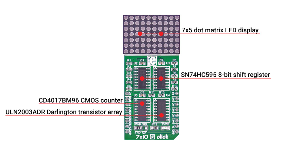
The dot matrix can also show scrolling text, thus fitting longer messages in small space. The pair of 8-bit SIPO shift registers drive the display. The current amplification necessary for driving the LEDs is performed by a Darlington Transistor array while a Johnson counter performs the necessary LED multiplex.
Specifications
| Type |
LED Matrix |
| Applications |
7x5 dot matrix text display for user interfaces |
| On-board modules |
SN74HC595 8-bit shift register, ULN2003ADR Darlington transistor array, CD4017BM96 CMOS counter |
| Key Benefits |
Displays letters in highly readable format, scrolling text capability |
| Interface |
SPI |
| Input Voltage |
3.3V or 5V |
| Click board size |
L (57.15 x 25.4 mm) |
Pinout diagram
This table shows how the pinout on 7x10 G click corresponds to the pinout on the mikroBUS??? socket (the latter shown in the two middle columns).
| Notes | Pin |  | Pin | Notes |
|---|
| CD4017 clock pin |
RC |
1 |
AN |
PWM |
16 |
RR |
CD4017 reset pin |
| 74HC595 reset |
RST |
2 |
RST |
INT |
15 |
NC |
|
| Latch of 74HC595 |
CS |
3 |
CS |
TX |
14 |
NC |
|
| SPI clock pin |
SCK |
4 |
SCK |
RX |
13 |
NC |
|
| SPI slave data out pin |
SDO |
5 |
MISO |
SCL |
12 |
NC |
|
| SPI slave data in pin |
SDI |
6 |
MOSI |
SDA |
11 |
NC |
|
| Power supply |
+3.3V |
7 |
3.3V |
5V |
10 |
+5V |
Power supply |
| Ground |
GND |
8 |
GND |
GND |
9 |
GND |
Ground |
Programming
Code examples for 7x10 G click, written for MikroElektronika hardware and compilers are available on Libstock.
Code snippet
This code snippet shows how to display scrolling text at medium speed.
01 void S7X10G_Task()
02 {
03     bool ind;
04     static bool called = false;
05     S7X10G_clearDisplay();
06
07     // scrolls given text
08     if ( !called )
09     {
10         S7X10G_drawText( "  Mikro Elektronika" );
11         S7X10G_scrollEnable( S7X10G_SPEED_MED );
12         called = true;
13     }
14     do
15     {
16         ind = S7X10G_refreshDisplay();
17         S7X10G_tick();
18         Delay_ms( 10 );
19     } while( ind );
20     called = false;
21 }
22
23 void main()
24 {
25     systemInit();
26     while( 1 )
27     {
28         S7X10G_Task();
29     }
30 }