Lora™ RF technology based 868MHz transceiver
LoRa 3 click is a LoRa™ technology based SRD transceiver, which operates at sub-gigahertz frequency of 868MHz. Thanks to the spread spectrum modulation feature, as well as the low power consumption, it is capable of achieving a long-range communication, immune to interferences. This click board™ features a complete LoRa™ stack onboard: it implements physical, network and MAC layers, allowing for easy operation via the UART interface. The transceiver is RED 2014/53/EU certified and compliant to ReACH and ROHS regulations, allowing for an easy integration into the final application, reducing development time, costs, and time to market.
Coupled with the AES128 message encryption, very small form factor, and low current consumption, Lora™ 3 click offers an easy and reliable solutions for developing low power, highly integrated IoT networks, security systems, alarm networks, and similar applications that require simple and reliable networking solutions
How does it work
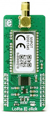
The heart of the LoRa 3 click is a wireless transceiver module from Mipot company, labelled as 32001345. It is the Lora™ RF technology-based long range transceiver, optimized for a robust wireless networking, immune to interferences. The network is implemented as a star topology, where endpoints work in duty cycle mode, significantly reducing the overall power consumption. This allows endpoint nodes to be battery operated.
The communication is done via the UART interface. A communication between the module and the host MCU starts with the MCU pulling the NWAKE pin to a LOW logic state. This will wake up the module, after which the module expects the 0xAA code. This code is a header of every data packet that has been sent or received. After the header, a command code is sent, followed by the payload and the checksum. After a complete packet has been received and its checksum is verified, the module pulls the NDATA_INDICATE (ND_IND) to a LOW logic level. After a short timeout, the data (message) is sent via the UART TX pin of the module, back to the host MCU. At the end of the communication cycle, the ND_IND pin is pulled to a HIGH logic level and the module goes into the sleep mode, waiting to be awakened again by the NWAKE pin. Every command from the host results with a response from the module in the same format, with the command code ORed with 0x80.
Lora 3 click can be configured to work as either END NODE or MASTER NODE, by using simple AT commands. While working as MASTER NODE, the click board™ can use a set of master-specific commands, such as the pairing command. This command will add the end node which requested pairing, to the master network table. While working as END NODE, LORA 3 click can issue slave specific commands/requests, such as the pairing request command, which will allow that end node to be paired with the master. However, the provided LoRa 3 click library offers easy to use functions, which simplify configuration and communication tasks. Their usage is demonstrated in the included example application.
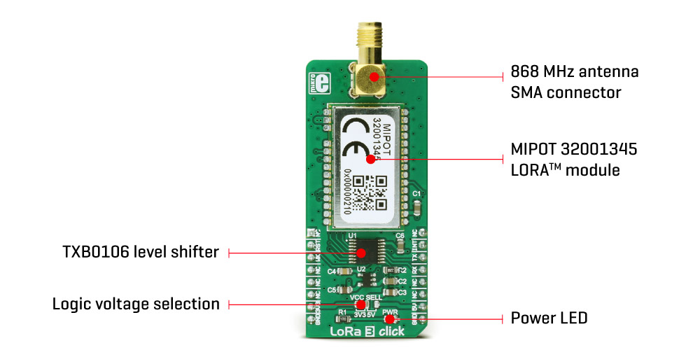
To allow interfacing with both 3.3V and 5V MCUs, this click board™ employs the TXB0106, a bidirectional level shifter and voltage translator from Texas Instruments. This translates the external voltage levels to acceptable levels that can be used on the Mipot LoRa™ module. All the I/O pins of the 32001345 Lora™ module are routed via this IC to the mikroBUS™ pins.
The NWAKE pin from the 32001345 Lora™ module is routed to the mikroBUS™ CS pin, while the UART RX and TX pins are routed to the appropriate mikroBUS™ UART pins, via the level shifter. ND_IND pin is routed to the INT pin of the mikroBUS™ - also via the level shifter - so it can be used to easily trigger an interrupt, or some other type of alert indicating that the module transmits data.
The NRST pin is routed to the mikroBUS™ RST pin and it is used to reset the device. It is internally pulled up with a resistor.
The LoRa 3 click board features a SMA connector so it can be equipped with the appropriate 868MHz antenna like THIS ONE. The onboard SMD jumper labeled as is used to select a voltage input for the level shifter for interfacing with 3.3V or 5V MCUs.
Specifications
| Type |
LoRa |
| Applications |
Lora™ 3 click offers an easy and reliable solutions for developing low power, highly integrated IoT networks, security systems, alarm networks, and similar applications that require simple and reliable networking solutions |
| On-board modules |
MIPOT 32001345, Lora™ RF technology-based long range transceiver |
| Key Features |
The click board™ features robust Lora™ RF technology based wireless networking, full network stack, message encrypting (AES128), easy to use UART interface and low power consumption |
| Interface |
UART |
| Input Voltage |
3.3V,5V |
| Click board size |
L (57.15 x 25.4 mm) |
Pinout diagram
This table shows how the pinout on LoRa 3 click corresponds to the pinout on the mikroBUS™ socket (the latter shown in the two middle columns).
| Notes | Pin |  | Pin | Notes |
|---|
|
NC |
1 |
AN |
PWM |
16 |
NC |
|
| Device Reset |
RST |
2 |
RST |
INT |
15 |
INT |
Data TX indication |
| Wake up |
WK |
3 |
CS |
RX |
14 |
TX |
UART transmit |
|
NC |
4 |
SCK |
TX |
13 |
RX |
UART receive |
|
NC |
5 |
MISO |
SCL |
12 |
NC |
|
|
NC |
6 |
MOSI |
SDA |
11 |
NC |
|
| Power supply |
+3.3V |
7 |
3.3V |
5V |
10 |
+5V |
Power supply |
| Ground |
GND |
8 |
GND |
GND |
9 |
GND |
Ground |
Onboard settings and indicators
| Label | Name | Default | Description |
|---|
| JP1 |
PWR.SEL |
Left |
Logic level voltage selection: Left position 3V3, right position 5V |
| LD1 |
PWR |
- |
Power LED indicator |
Software support
We provide a library for LoRa 3 click on our LibStock page, as well as a demo application (example), developed using MikroElektronika compilers and mikroSDK. The provided click library is mikroSDK standard compliant. The demo application can run on all the main MikroElektronika development boards.
Library Description
Initializes and defines UART bus driver and driver functions which offers a choice to writing on EEPROM, reading from EEPROM, communication with other LoRa Mipot 32001345 click and ability to pairing between MASTER and END NODE. For more details check the documentation.
Key functions:
LORA3_RETVAL_T lora3_writeEeprom( uint8_t address, uint8_t nBytes, uint8_t *dataIn ) - The function writes data to EEPROM.
LORA3_RETVAL_T lora3_enablePairing( uint8_t state ) - The function enables or disables network the pairing procedure.
LORA3_RETVAL_T lora3_txMessage( uint8_t *dataIn, uint8_t nBytes, uint32_t destinationID, uint8_t option ) - The function performs the transmission of radio frames.
LORA3_RETVAL_T lora3_getPairingRequest( void ) - Function requests a pairing to a network.
void lora3_process() - The function executes reading indications and forwards indications to the handler.
Examples Description
- The application is composed of three sections:
- System Initialization - Initializes peripherals and pins.
- Application Task - (code snippet) - Checks is indication occurred.
void applicationTask()
{
 lora3_process();
}
Additional Functions:
- void indicationHandler( uint8_t *cmd, uint8_t *plSize, uint8_t *plBuffer ) - Logs results on USB UART when device gets indication on command.
Other mikroE Libraries used in the example:
Additional notes and information
Depending on the development board you are using, you may need USB UART click, USB UART 2 click or RS232 click to connect to your PC, for development systems with no UART to USB interface available on the board. The terminal available in all MikroElektronika compilers, or any other terminal application of your choice, can be used to read the message.