How does it work?
The remote reading of heat meters can take place in different ways. Besides the remote reading, the whole collection of various meters can be remotely controlled over M-Bus, making it a complete housing solution. The latter is a logical continuation/extension of the technical development of consumption meters and is realizable with the help of the M-Bus Click.
In order to realize an extensive bus network with low cost for the transmission medium, a two-wire cable was used together with serial data transfer. In order to allow remote powering of the slaves, the bits on the bus are represented as follows:
- The transfer of bits from master to slave is accomplished by means of voltage level shifts. A logical "1" (Mark) corresponds to a nominal voltage of +36 V at the output of the bus driver (repeater), which is a part of the master; when a logical "0" (Space) is sent, the repeater reduces the bus voltage by 12 V to a nominal +24 V at its output.
- Bits sent in the direction from slave to master are coded by modulating the current consumption of the slave. A logical "1" is represented by a constant (versus voltage, temperature and time) current of up to 1.5 mA, and a logical "0" (Space) by an increased current drain requirement by the slave of additional 11-20 mA. The mark state current can be used to power the interface and possibly the meter or sensor itself.
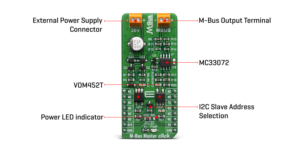
As mentioned above, M-Bus standard has predefined voltage levels and principle of work. In order to achieve that, M-Bus Master click has built in complete solution for master node on the network, based on MC33072ADR2G ??? monolithic, single supply 3 - 44 V operational amplifier from ON Semiconductor. Besides the operational amplifier, this click board has all other needed components needed to achieve a complete analog solution which, on its output, fulfils the M-Bus voltage and current predefined specifications.
This Click board™ also has VOM452 onboard ??? the analog, high hpeed, high noise immunity, 1 MBd optocoupler, from Vishay Semiconductors. Theese high speed optocouplers, each consists of a GaAlAs infrared emitting diode, optically coupled with an integrated photo detector and a high speed transistor. The photo detector is junction isolated from the transistor to reduce miller capacitance effects. The open collector output function allows circuit designers to adjust the load conditions when interfacing with different logic systems such as TTL, CMOS, etc. All these features improve the reliability of the whole circuit, while enabling the galvanic isolation.
M-Bus Master click offers a selection between 3.3V and 5V operation, with the onboard SMD jumper, labeled as PWR SEL. This allows both 3.3V and 5V MCUs to be interfaced with this Click board™.
Specifications
| Type |
RS232 |
| Applications |
Remote sensor reading, remote control over M-Bus, smart house |
| On-board modules |
MC33072ADR2G, a monolithic operational amplifier from ON Semiconductor |
| Key Features |
Galvanicaly isolated, Master node |
| Interface |
UART |
| Compatibility |
mikroBUS |
| Click board size |
L (57.15 x 25.4 mm) |
| Input Voltage |
3.3V or 5V |
Pinout diagram
This table shows how the pinout on the M-Bus Master click corresponds to the pinout on the mikroBUS™ socket (the latter shown in the two middle columns).
| Notes |
Pin |
 |
Pin |
Notes |
|---|
| |
NC |
1 |
AN |
PWM |
16 |
NC |
|
| |
NC |
2 |
RST |
INT |
15 |
NC |
|
| |
NC |
3 |
CS |
RX |
14 |
TX |
UART TX |
| |
NC |
4 |
SCK |
TX |
13 |
RX |
UART RX |
| |
NC |
5 |
MISO |
SCL |
12 |
NC |
|
| |
NC |
6 |
MOSI |
SDA |
11 |
NC |
|
| Power Supply |
3.3V |
7 |
3.3V |
5V |
10 |
5V |
Power Supply |
| Ground |
GND |
8 |
GND |
GND |
9 |
GND |
Ground |
Onboard settings and indicators
| Label |
Name |
Default |
Description |
|---|
| LD1 |
PWR |
- |
Power LED Indicator |
| JP1 |
VCC SEL |
Left |
Power supply voltage selection: left position 3.3V, right position 5V |
Software Support
We provide a library for the M-Bus Master Click on our LibStock page, as well as a demo application (example), developed using MikroElektronika compilers. The demo can run on all the main MikroElektronika development boards.
Library Description
Initializes and defines UART bus driver, and defines driver's functions for writing data on the M-BUS terminal.
Key functions:
void mbusmaster_write_byte ( uint8_t input ) - Write one byte data
Examples description
The application is composed of three sections :
- System Initialization - Initializes UART module
- Application Initialization - Initializes driver init
- Application Task - Sends a message [MikroE] to the M-BUS connector every 2 seconds.
void application_task ( )
{
    char tmp;

    for ( tmp = 0; tmp < 9; tmp++ )
    {
        mbusmaster_write_byte( demo_message_data[ tmp ] );
    }

    mikrobus_logWrite( ">> MESSAGE SENT <<", _LOG_LINE );
    Delay_ms(2000);
}
Note:
- M-Bus master communication works at 36v.
- This click acts only as 'master', therefore it must be connected to appropriate 'slave'.
The full application code, and ready to use projects can be found on our LibStock page.
Other mikroE Libraries used in the example:
Additional notes and informations
Depending on the development board you are using, you may need USB UART click, USB UART 2 click or RS232 click to connect to your PC, for development systems with no UART to USB interface available on the board. The terminal available in all MikroElektronika compilers, or any other terminal application of your choice, can be used to read the message.
mikroSDK
This Click board™ is supported with mikroSDK - MikroElektronika Software Development Kit. To ensure proper operation of mikroSDK compliant Click board™ demo applications, mikroSDK should be downloaded from the LibStock and installed for the compiler you are using.
For more information about mikroSDK, visit the official page.
Resources
Downloads