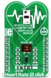
Heart Rate 5 click is the optical biosensor Click board™ which can be used for the heart-rate monitoring (HRM), as well as the peripheral capillary oxygen saturation monitoring (SpO2). This Click board™ employs a very sensitive analog front-end IC with high dynamic range, which ensures accurate and reliable readings. This analog front-end IC is coupled with the optical front end, which consists of the top-of-the-class integrated BIOFY® sensor, which features two green LEDs, one red LED, one infrared LED, and two photodiodes (PD), offering very accurate HRM and SpO2 readings.
The analog front-end IC features a trans-impedance amplifier circuitry with programmable gain, which provides linear voltage changes for the 22bit ADC. It also provides individual DC offset subtraction for the LED and ambient light phases, as well as the ambient light influence cancellation at the ADC output. The signal path within the IC is kept differential, ensuring the lowest possible amount of interferences and noise. These features allow Heart Rate 5 to achieve reliable and accurate readings. It can be used to develop applications based on the heart rate monitoring, pulse oximetry measurements, calorie expenditure, and similar health-related applications.
Pulse oximetry or SpO2
Oxygen saturated blood absorbs light in the red/IR part of the spectrum different than the unsaturated blood. Pulse oximeters measure the oxygen saturation of the blood, or more precisely, the percentage of hemoglobin molecules in the blood, saturated with oxygen. For a healthy adult person, the peripheral capillary oxygen saturation (SpO2) percentage ranges from 95% to 100%. Heart Rate 5 click can provide the SpO2 measurement, by simply placing the index finger over the optical sensor.
Heart Rate Monitoring or HRM
While the blood passes through the capillary blood vessels, they expand and dilate. Their light reflectance index changes accordingly. This is the basis of the photoplethysmogram (PPM), a method used for the volumetric measurement of an organ, or in this case - blood vessels. The heart rate signal is calculated according to the current changes in transmission and reflection of the green light, sensed by the PD element. The Heart Rate 5 click can provide the HRM readings, by simply placing the index finger over the optical sensor.
How does it work?
Heart Rate 5 click consists of an analog front end and the optical front end. The main task of the analog front-end IC is to drive LEDs and condition the signal received by the photodiode (PD), by eliminating the background noise and ambient light influence on the measurement. Besides that, it also provides conversion of the measurement into a digital information, which can be used by the MCU. For the conversion to be accurate, the analog front-end device must not introduce any artifacts into the readings.
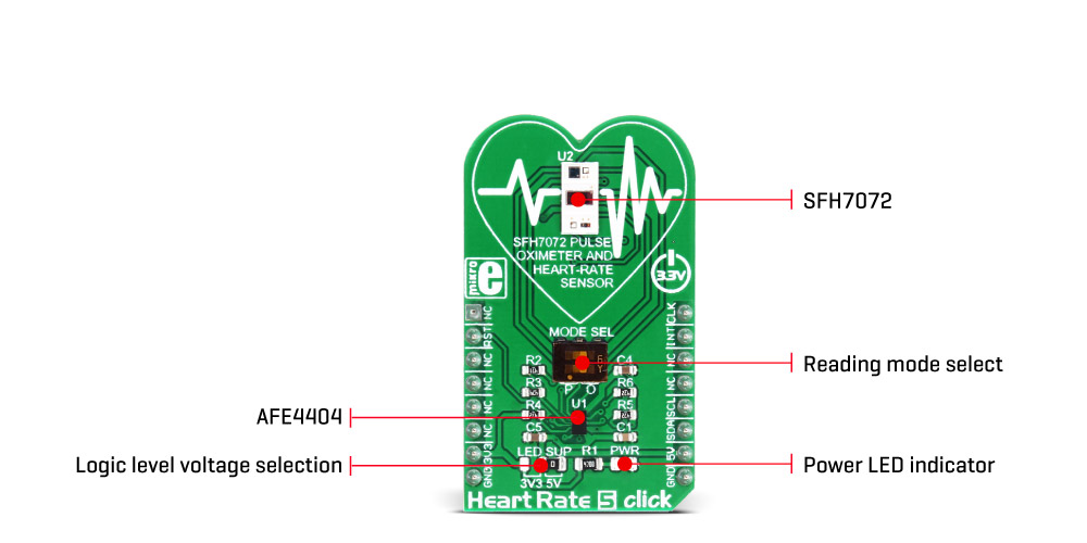
To achieve accurate measurements, Heart Rate 5 click employs AFE4404, an integrated analog front end (AFE) device, used for optical heart-rate monitoring and bio-sensing, from Texas Instruments. This IC supports up to three switching LEDs and a single PD element. The current from the PD element is converted to a linear voltage by the means of the integrated trans-impedance amplifier section (TIA) with a programmable gain so that it can be sampled by the AD section, which features a 22bit ADC converter. The signal chain is kept fully differential throughout the receiver channel, in order to achieve good rejection of common-mode noise, as well as the noise from the power supply. The AFE IC uses the I2C communication, with its pins routed to the corresponding mikroBUS™ I2C pins.
As the optical front end, Heart Rate 5 click uses the top-of-the-class integrated BIOFY® SFH 7072 sensor, from OSRAM, which features two green LEDs, one red LED, one infrared LED, and two PDs, of which one is a broadband PD used for the HRM, while the other is the IR band cut PD, used for the SpO2 readings. These LEDs are specially designed for the HRM and SpO2 measurement applications, offering a set of calibrated wavelengths for both light-emitting diodes (LED) and photo-sensing diodes (PD). Since the SF7072 sensor offers more elements than the ALS can support, the choice is made by flipping the onboard SMD switch labeled as MODE SEL: the choice can be made between the broadband PD for the HRM readings and the IR band PD for SnO2 readings. Both poles of the switch SW1 need to stay in the same position (both to the left, or both to the right), as they are routed to each end of the respective PD element.
The analog front end works with the periodically repeated operations (a pulse repetition frequency or PRF). There are four sampling phases per cycle. The four different readings are stored in separate 24bit output registers. There are also four filters on the TIA output, which are used to allow pulses from the PD to pass through the ADC, isolating the time when the emitting LEDs are ON, switching to the different filter in every sampling phase. The sampling phases are determined by the LED modes: two LED mode or three LED mode. This affects which LEDs are pulsed during the corresponding sampling cycles – LED1 and LED2, or LED 1, LED 2 and LED 3.
The AFE4404 IC also incorporates a DAC, used to cancel the DC offset from the PD. When the TIA gain is set to a high value, it will amplify the DC component of the PD signal. To allow ADC conversion, this component needs to be removed from the signal path, so the DAC with the opposite current direction is introduced at the input stage, based on the existing DC offset. This allows for higher amplification of the signal from the PD, and thus, more useful AC signal detection sensitivity.
The LED drivers allow 6 bit of LED current control for each channel individually. This allows 63 steps between 0 and 50mA. This range can be doubled to 100mA. The LED driver voltage can be set by the onboard SMD jumper, labeled as the LED SUP. It offers a selection between 3.3V and 5V. The ADC_RDY pin provides an interrupt to the host MCU, saving it from having to constantly poll the sensor for data. This pin is set to a HIGH logic level when the PRF cycle ends, allowing four output data registers to be read. The PRF can vary between 10 up to 1000 samples per second. This pin is routed to the INT pin of the mikroBUS™.
The AFE4404 IC can be clocked both internally and externally. For precise and synchronized measurement, It is advised to drive the Heart Rate 5 click by the same clock as the host MCU. The input clock can go up to 60MHz, but the internal divider of the IC has to be set so that the clock stays within the range from 4MHz to 6MHz. When driven by the internal clock, the device runs at 4MHz. By default, the external clock input is selected. The clock signal can be introduced via the PWM pin of the mikroBUS™.
After the power-on, the AFE IC requires a reset. The RESETZ pin of this IC is routed to the RST pin of the mikroBUS™, allowing it to be reset by the host MCU. Pulling this signal to a LOW logic level for about 25 µs to 50 µs will cause a reset of the device. If this pin is pulled for more than 200 µs, it will put the device into the POWER DOWN mode. The device can also be reset by setting a bit in the appropriate register, via the I2C. This pin is pulled to a HIGH logic level by the onboard pull-up resistor.
More information about the registers and how to set them can be found in the AFE4404 IC datasheet. However, included library contains functions that allow easy configuration and use of the Heart Rate 5 click. The included exemplary (demo) application demonstrates their functionality and can be used as a reference for a custom design.
Specifications
| Type |
Biomedical |
| Applications |
It can be used to develop applications based on the heart rate monitoring, pulse oximetry measurements, calorie expenditure, and similar health-related applications. |
| On-board modules |
AFE4404, a compact integrated analog front end (AFE) device for optical heart-rate monitoring and bio-sensing, from Texas Instruments; BIOFY® SF7072 integrated LED and PD optical front end, from OSRAM. |
| Key Features |
High dynamic sensitivity, three integrated LED drivers with independently programmable currents, ambient light and DC offset cancellation, internal/external clock source, top-of-the-class integrated LED and PD optical calibrated front-end from OSRAM. |
| Interface |
I2C |
| Input Voltage |
3.3V,5V |
| Click board size |
M (42.9 x 25.4 mm) |
Pinout diagram
This table shows how the pinout on Heart Rate 5 click corresponds to the pinout on the mikroBUS™ socket (the latter shown in the two middle columns).
| Notes | Pin |  | Pin | Notes |
|---|
|
NC |
1 |
AN |
PWM |
16 |
CLK |
External clock input |
| Reset/Power-down |
RST |
2 |
RST |
INT |
15 |
INT |
ADC_RDY/Interrupt |
|
NC |
3 |
CS |
RX |
14 |
NC |
|
|
NC |
4 |
SCK |
TX |
13 |
NC |
|
|
NC |
5 |
MISO |
SCL |
12 |
SCL |
I2C clock |
|
NC |
6 |
MOSI |
SDA |
11 |
SDA |
I2C data |
| Power supply |
+3.3V |
7 |
3.3V |
5V |
10 |
+5V |
Power supply |
| Ground |
GND |
8 |
GND |
GND |
9 |
GND |
Ground |
Onboard settings and indicators
| Label | Name | Default | Description |
|---|
| LD1 |
PWR |
- |
Power LED indicator |
| JP1 |
LED SUP |
Right |
LED driver voltage selection: left position 3.3V, right position 5V |
| SW1 |
MODE SEL |
Right |
Photo-diode type selection (anode): left position HRM (P), right position SpO2 (O) |
Software support
We provide a library for Heart Rate 5 click on our Libstock page, as well as a demo application (example), developed using MikroElektronika compilers. The demo application can run on all the main MikroElektronika development boards.
Library Description
The library provides generic functions for communicating with the Click board™.
Key functions:
void heartrate5_hwReset();- Function for doing a hardware reset on a click board.void heartrate5_init();- Initializes the click board for communication.uint32_t heartrate5_getLed2_aled2val(void);- Test if the finger is placed on the sensor.uint32_t heartrate5_getAled1val(void);- Get the raw pulse analog value that will be displayed on MikroPlot.
Examples Description
The demo application is composed of three sections:
- System Initialization - Initializes GPIO, I2C and log structures.
- Application Initialization - Configures the microcontroller for communication and initializes the click board. Also, the start signal is sent to the MikroPlot application.
- Application Task - This section shows how the data is processed and sent to the MikroPlot application.
void applicationTask()
{
 uint32_t sensorValue;

 if(heartrate5_getLed2_aled2val() < 10)
 {
 if(flag==1)
 {
 sensorValue=heartrate5_getAled1val();
 mikroPlot(ms_counter,sensorValue);
 flag=0;
 }
 }
 else
 {
 ms_counter=0;
 }
}
Additional functions:
void mikroPlot(uint32_t ms_count, uint32_t measurement); - Functions that prepares and sends data to the MikroPlot application.
The full application code, and ready to use projects can be found on our Libstock page.
mikroE Libraries used in the example:
- Conversions Library
- C_String Library
- I2C Library
- UART Library
Additional notes and information
Depending on the development board you are using, you may need USB UART click, USB UART 2 click or RS232 click to connect to your PC, for development systems with no UART to USB interface available on the board. The terminal available in all MikroElektronika compilers, or any other terminal application of your choice, can be used to read the message.
mikroSDK
This click board is supported by mikroSDK - MikroElektronika Software Development Kit. To ensure proper operation of mikroSDK compliant click board demo applications, mikroSDK should be downloaded from the LibStock and installed for the compiler you are using.
For more information about mikroSDK, visit the official page.