How does it work?
One Shot click is equipped with the LTC6993-2, a monostable multivibrator (also known as a ???one-shot??? pulse generator) with a programmable pulse width of 1??s to 33.6 seconds, from Analog Devices. The LTC6993-2 is part of the TimerBlox® family of versatile silicon timing devices. A single resistor, RSET, programs an internal master oscillator frequency, setting the LTC6993's time base. The output pulse width is determined by this master oscillator and an internal clock divider, NDIV, programmable to eight settings from 1 to 221.
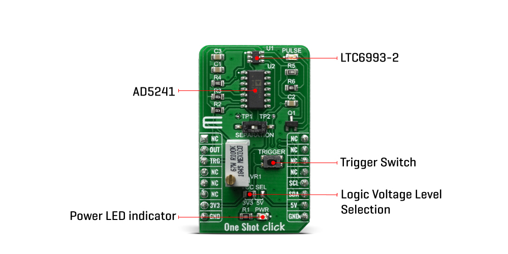
The output pulse is initiated by a transition on the trigger input (TRIG). Each part can be configured to generate positive or negative output pulses. The LTC6993-2 is available in four versions to provide different trigger signal polarity and retrigger capability. Besides that, LTC6993-2 also offers the ability to dynamically adjust the width of the output pulse via a separate control voltage, brought to the SET pin of the IC. Simple trimmer or potentiometer could be used, however due to reliability reasons, on One Shot Click, AD5241 digital potentiometer is used for that purpose. The word is about a 256-position digital potentiometer with low temperature coefficient (30 ppm/°C), also from Analog Devices. The AD5241 communicates with the microcontroller over the standard I2C interface, so that user can easily control and precisely calculate the output pulse width just with simple setting the wiper value in the AD5241 registers.
One Shot Click also contains the multi-turn trimmer wired as a a resistor divider between V+ and GND and brought to the DIV pin of the LTC6993-2. The DIV pin is the programmable divider and polarity input. The polarity input which pin voltage is internally converted into a 4-bit result (DIVCODE). The MSB of DIVCODE (POL) determines the polarity of the OUT pins. When POL = 0 the output produces a positive pulse. When POL = 1 the output produces a negative pulse. That way, user can easily set the output pulse width range and polarity, just by setting the desired voltage on the mentioned trimmer (VR1). This click board also contains test points in order to ease the access to the referent voltage to the user. One can simply separate the trimmer from the rest of the circuit using the separation switch (SW1), then precisely set and measure the desired voltage and then turn the switch back in the ON position.
One Shot Click is equipped with on-board SMD jumper labeled as the VCC SEL, which is used to select the operating voltage level, consequently limiting the amplitude of the output signal in respect to the selected voltage. That enables a selection between 3.3V and 5V operation, with the onboard SMD jumper, labeled as VCC SEL. This allows both 3.3V and 5V MCUs to be interfaced with this Click board™.
Specifications
| Type |
Signal generator,Clock generator |
| Applications |
Ideal choice for applications such as watchdog timers, frequency discriminators, missing pulse detection, Envelope Detection and more. |
| On-board modules |
LTC®6993 - a monostable multivibrator (also known as a ???one-shot??? pulse generator) with a programmable pulse width from analog devices
AD5241 - 256-Position Digital Potentiometer
|
| Key Features |
Configurability for positive or negative output pulse, fast recovery time, 70??A supply current, CMOS output driver 20mA sources/sinks and many more |
| Interface |
GPIO,I2C |
| Compatibility |
mikroBUS |
| Click board size |
M (42.9 x 25.4 mm) |
| Input Voltage |
3.3V or 5V |
Pinout diagram
This table shows how the pinout on One Shot Click corresponds to the pinout on the mikroBUS™ socket (the latter shown in the two middle columns).
| Notes |
Pin |
 |
Pin |
Notes |
|---|
| |
NC |
1 |
AN |
PWM |
16 |
NC |
|
| Output signal |
OUT |
2 |
RST |
INT |
15 |
NC |
|
| Trigger input |
TRG |
3 |
CS |
RX |
14 |
NC |
|
| |
NC |
4 |
SCK |
TX |
13 |
NC |
|
| |
NC |
5 |
MISO |
SCL |
12 |
SCL |
I2C Clock |
| |
NC |
6 |
MOSI |
SDA |
11 |
SDA |
I2C Data |
| Power Supply |
3.3V |
7 |
3.3V |
5V |
10 |
5V |
Power supply |
| Ground |
GND |
8 |
GND |
GND |
9 |
GND |
Ground |
Onboard settings and indicators
| Label |
Name |
Default |
Description |
|---|
| LD1 |
PWR |
- |
Power LED Indicator |
| JP1 |
VCC SEL |
Left |
Power supply voltage selection: left position 3V3, right position 5V |
| SW1 |
SEPARATION |
Right |
VDIV voltage separation switch |
Software Support
We provide a library for the One Shot Click on our LibStock page, as well as a demo application (example), developed using MikroElektronika compilers. The demo can run on all the main MikroElektronika development boards.
Library Description
The library covers all the necessary functions to control One Shot Click. User can use functions to set or check state of AD5241, set or clear trigger pin and check output pin.
Key functions:
void oneshot_setTrig( uint8_t state ) - Changes the state of trigger pin.uint8_t oneshot_checkOut() - Checks the state of output pin.float oneshot_getR() - Calculates resistance of AD5241.
Examples description
The application is composed of three sections :
- System Initialization - Initializes I2C and LOG structures, sets CS pin as output and RST pin as input.
- Application Initialization - Initialization driver enables I2C and also starts write log.
- Application Task - (code snippet) This example demonstrates the use of One Shot click. When value 0x18 is applied on AD5241, trigger pin is cleared and ressistance between TP1 i TP2 is set to 27 kohm, One Shot click produces one 0.5s pulse.
void applicationTask()
{
    oneshot_setTrig( 0 );
}
The full application code, and ready to use projects can be found on our LibStock page.
Other Mikroe Libraries used in the example:
Additional notes and informations
Depending on the development board you are using, you may need USB UART click, USB UART 2 click or RS232 click to connect to your PC, for development systems with no UART to USB interface available on the board. The terminal available in all MikroElektronika compilers, or any other terminal application of your choice, can be used to read the message.
mikroSDK
This Click board™ is supported with mikroSDK - MikroElektronika Software Development Kit. To ensure proper operation of mikroSDK compliant Click board™ demo applications, mikroSDK should be downloaded from the LibStock and installed for the compiler you are using.
For more information about mikroSDK, visit the official page.
Resources
Downloads